ChipTrick The Kit
Let's get start making electrical muisc device

This project named "Chip Trick" is designed for beginners for electricity. and this is for someone who wants to build something sound oneself. Pushing button will get the chip tune taste noise . Just putting button in the circuit will drive noise as something beats. you can get something groove just push it.
there is only 10 components. Main part is build putting the components onto the board and solder it. Then connect batteries and plug to guitar amp or line mixer (I recommend that to be connect it to mixer)
you can put it into any enclosure you like. Yes, you can use it as is.
This kit has no power switch. Get off your batteries when you finish your playing.
Free soldering area is for practice to use soldering iron. you can also add something another circuits to expand this machine. you can find schematic or something at the bottom of this page
What kind of sound we can get?
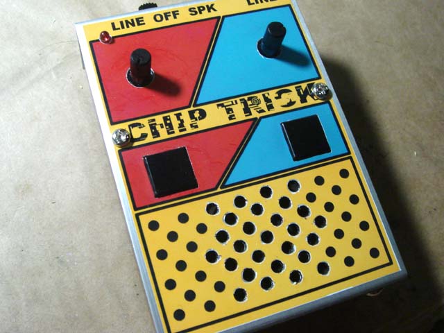
Never mind, Just check it out this video. this is the very first version that I build. I build it on universal board. and put it into aluminum enclosure.
this kit can also put in to same enclosure. if you play this in your hand, the you should better put this in to something enclouser. It can be used as accents On the stage or at the DJ play.
You can cut this board into two. one is sound generator and the other is controller. Draw the cable and make this remote controlled.
you can use it more powerful electrical percussion if you change switches more big and tough one.
all the pictures on this page can enlarge by clicking. let's get start building by checking pictures together.
check the compornents out!
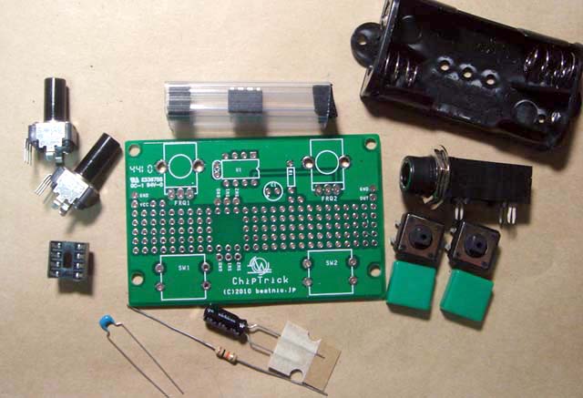
Main component is just one chip CPU only. And we need a register and 2 capacitors. One capacitor is chemical and the other one is made from ceramic that's tiny blue ship.
All the components are in the plastic bag except wire to connect PCB, battery box and output jack. Just a meter of wire should be enough for this project.
IC and chemical capacitor has its directions. Don't put them in wrong way. Anyway this project has so few parts. You can do it if you build it carefully.
Open the plastic bag and check your components closely.
chemical capacitor has the values on its body in simple way. you can read it as '10μF 50V'.
But ceramic capacitor is too small to print some letters or numbers as its values on its body. And register has round body and also not easy to print letters on it body. they have another way to display their values on its bodies.
Register has stripe with some colors on its body. stripe can be checked from any directions. Each color has each numbers. and color set means values. it's called as 'color code'. please check it, by another web page or something.
in this project, We use register that has following colors. they have "Brown", "Black", "Orange" and "Gold" stripes. this means 10kΩ and 1% Error margin.
And you can find the numbers on the small body of ceramic capacitor. And it should be "104". This numbers means 0.1μF. We use "u" instead of "μ" for easy to explain.
before start soldering...
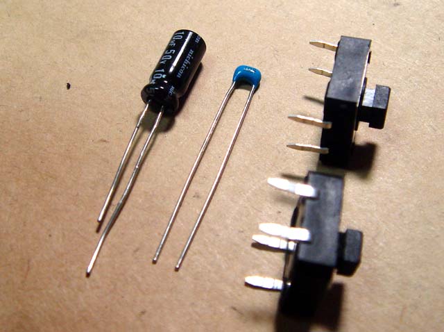
Before soldering, we need re-form the legs of the components. Some part has no need to do this. But in this kit, some components need re-form its legs. Use longnose pliers for do this.
The picture shows components that needs re-form its legs.
Rough construction may be OK when it just after finished. But it may get trouble later.
you should better build your PCB quite neat.
Let's get first soldering

We use just one register in this project. it's 10kΩ.
10kΩ
means value of register. And there is so many variations of it. We use "1/4w carbon register" for this project. it's just little big for this board. You can use more smaller register called "1/6w". You can get it so cheap price And we can use both type of registers in safe in this design.
Put register at "R1" on the PCB and ceramic capacitor should be C2. Turn your board and check the positions, then solder it.
Solder may melt quickly if it touch to the soldering iron. We should put the heat onto the rand that the doughnut around the hole and the legs of components. Then add solder onto them. Putting heats is just a second and put solder next a second. Total time may be 2 second or so.
Too much heat may get damage onto components.

Don't imagine clock. Feel the beats. Quarter note in 120bpm means just a half second. One bar is 2 second.
count the beat just same as walking. 1 point should be finished in a bar.
When you can do it well, it's looks almost like wet and moist. Melting solders get together each components tightly.
If it's ok, then cut off the rest of the legs of components. If you can do well within 2 second, there is no damage for the components, but you should better keep their legs for heat sink untill finish soldering.
The essence of soldering is quick and certain.
Let's put the socket

Check the direction for IC socket. See the pictures on the PCB. Then turn down the board. you may drop the socket. Never mind, use Scotch tape to fix the positions. Stop wondering to use something another tool for getting good results.
Use solder with flux. It will help your soldering. but if you put heat for overtime, flax will gone. and it not good for well soldering. when you feel it too long time to do, then stop adding heat. Remember that 2 second is the time limit for almost every components. Cool down your PCB and components enough, and clean your tips of soldering iron. Then starting again with fresh solder with flax. It should get more good result.
if it looks having good contact, it's not enough. We must get wet and moist feeling
Let's put chemical capacitor

Chemical Capacitor has directions. check the picture just one before . you can find round mark just right side of the socket with "C1". you can find "+" mark in the circle. put the longer leg into this hole and short one is another . you can also find "-" mark at the body of capacitor.
if you get mistake on the direction for IC then you can recover when you put IC on it, but chemical capacitor is soldered directly onto the board. when you got mistake, you must add another heat onto the capacitor to get off from PCB. it may get damage to the components. check them closely.
if you want to put this board into something enclouser, lay down your capacitor on to the board. it's too tall to do it.
PCB is almost finished

Many years ago, semiconductors was most weak components with the heat. Some of them are broken by heat of soldering iron. Now a days, they are getting strong. And the most weak components with the heat may be chemical capacitors or switches made by plastics now. they have metal legs, but it's too short from soldering point to plastic part. The heat from soldering iron may melt its bodies.
But don't waste time to wondering if it's ok or not. Put the heat enough to build them tight. it's not easy to find that not enough soldering or broken by heat. But if you do it within 2 second, components should be in safe. there should be not enough soldering.


Is your legs of switch is stretched? that is the big point of this project. When you play this gadgets, you may get higher with your sound and the switch may be hit so tightly more than you feeling. Yes! I guarantee it.
Put the legs of your switch more deeply untill the hip of the switch should sit down on the PCB.
check the picture. left is OK, and right is NG.
I've guided you for soldering. but there is method to do this. Notice that the height of each components. we solder the components that has same height at a time.
Put something under the PCB to keep it flatly. Melting solder behave as liquid. if it not flat, solder may be flowed.
Using a piece of wood block or something as a pillow may be useful for soldering.
Make it easy and simple.
The legs of the VR to fix onto the board is most hard to soldering in this project. Put enough heat and solder to fix it to the board.
OK, it's finished. Put the IC on the board. don't forget check it direction.
Preparing for next steps

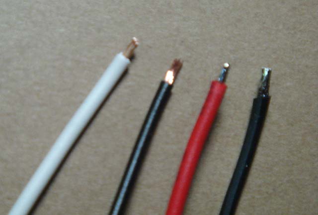
We should better prepare to solder out side of the PCB. Put the wire on the the battery box and output jack just same as the picture. about the output jack you may find 2 pin at the hip (not have mouse side) there is another function each other.
"out" is right side pin. To avoid having mistake, Use wire with different color at the same area. Battery line is most important for every machine. please check it closely. the spring on the battery box is "GND".
The most hard point for the beginner for handling soldering iron may be using wire. If you take enough time to solder wire then the vinyl may be melt. You should solder it as quick as you can.
Some kind of nickel plated terminal may get rusted. It not easy to find from just only its looks. Shine them with metal part of your plier or something and put enough heat. Never mind.
It's not easy. You may get fault and melt them at the first time. Try them and get the feelings. that's only way to do them well.
Finish!

This is Actual wiring diagram. It's so easy and simple. Connect "+" line of batteries to "VCC". it may be red. And "-" line to "GND" on the board. it may be Black. "GND" means Grand. Grnand is base voltage level to measure it. There is small rule. It should be called as de facto standard or so.
power line should be used as red line. And GND line black.
And tip line of output jack is connected "OUT" and another line go to "GND". if you solder them through the hole then it's not easy to break.
There is the tips for well soldering.
Wires are so weak for the heat. So to make it more shorter time to soldering to the terminals, you should better do pre-soldering for wires.
One more step to soldering will make you feel a bother. But it will make your soldering technique up one more. Trying and trying again is good teacher for soldering.
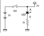
Adding power switch
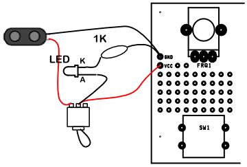
This kit has no power switch. But if you want, you can add it on your kits. Get it from somewhere at the web shop or so, then connect just like this.
If you don't need LED. then you can ommit them. Schematic is just like this.
If your LED is bright, then 1k is ok for this. When you feel that's dark, then change the value of current limitting resister. About the value, please learn another pages.
this technic is so simple but useful. please learn it. and use it anywhere you want.
Let's mod! (Get more than noise)
Let's start over here. At first, change the software of Chiptrick. (The kit that I ship includes Version 2 chip, now)
Without hardware changes, you can get another sound from chiptrick by changing software inside of the chip. check the methods to re-write software around the web. I can provide pre-programed CPU only. use kit page.
There is 3 mode. You can change it by turning power on with pushing SW1 or SW2. You should better to add power switch to change the mode easy.
- Chip Trick mode
- Do nothing. Just power on. it's just normal chip Trick mode
- Pulse wave mode
- Power on with SW1.
You can get 2 different pitch by SW1 and SW2. Pitch of SW1 can change by tweaking of VR1. And VR2 can also change the pitch of SW2. - R2D2 mode
- Power on with SW2.
SW1 can get random pitch. VR1 can change rate. SW1 get random noise. VR2 have no functions.
in 'Pulse wave mode', you can play it as samba whistle or something. And you can change pitch when you get the sounds.
You can push both switches at a time. then you can get noisy sounds. It's pseudo-ring modulation sounds. Enjoy it.
R2D2 is based on the name of Droid at 'Star Wars'. Using this mode, you can talk with him. Try it if you have a friend who is the same kind of R2D2, and give me report.
Adding more mod (Drive small speaker)
After the release of ChipTrick, it's added so many kind of modifications by many people. Most of all add the speaker at first. They had added power amp chip inside of their enclosure. So, I will try to smae thing with the people who get it.
The noise sound that getting from ChipTrick is just pulse wave but it's frequency is changed every single wave. So we can't feel its pitch from it. And we feel it as noise. this is the trick of "ChipTrick".
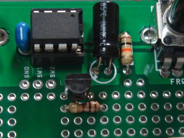
Anyway chipTrick puts just on / off only. there is no mid levels. We can drive speaker just like relays. Just only one transistor can drive speaker enough.
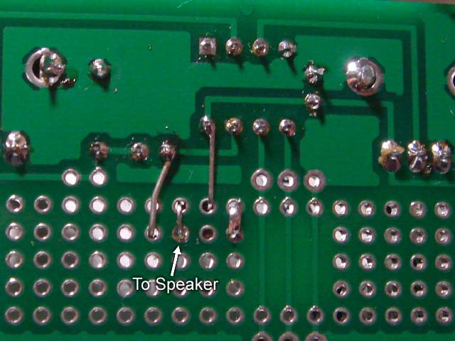
This mods needs a transistor, a resistor for base of transistor and a speaker. There is schematic and picture of free soldering space. Check them out.
I use 2SC2120 for this mod. We need more than 500mA for Ic of transistor. Several ohm for DC resistance of speaker is so tough for usual use transistors. they can get only 150mA or so. Chose more tough one for this mods.
Any NPN transistors may use in this methods. sound charactor is ruled by kind of speakers and enclosures. Never mind, You can use any one if it can draw out over 500mA. I can provide same transistor that I use at my kit page. check it out also. and also check the differences of pin structure of Japanese style and the others. Japanese one is E,C,B from left.
When you feel low your speaker then put it into enclosure. Nakid speaker can't drive air to get loud sound because of the air rotations around edge of unit. So you can get more loud sound by using Thin board that has small holes to cut the air flow around the edge of unit, instead of using the enclosure.
For Chiptrick, just carton box for chocolate may be enough. Try that and draw out the true power of your small speaker.
Remote Trick
this kit includes plastic knob pots. It makes this kit easy to build. But when you use it on your stage performance and getting excite you may pluck it. Someone want to change it more tough one. Get metal shaft pot and change it.
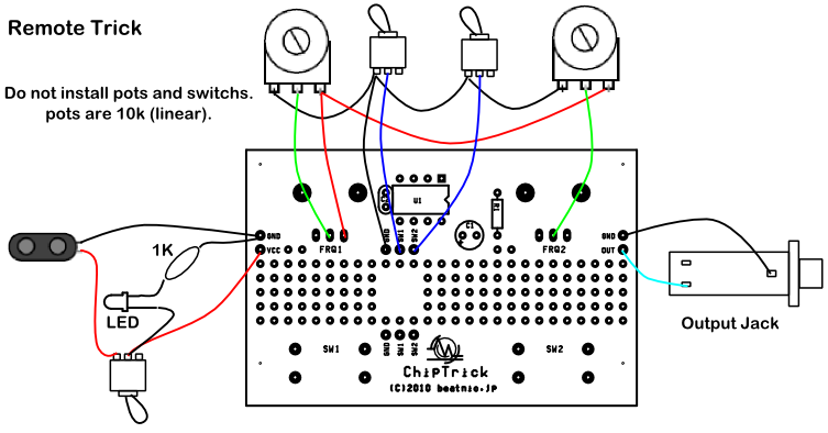
This is the "Remorte Trick"'s actual wiring diagram. Do not install plastic pot on your board when you use another pot that you get. About the values of pot, my recommendation is 10k linear. You can use any value for this schematic more than 1k. Too small value may get more battery power. there is nothing good. Too big value may get noise from out side. when you get the noise then there is no problems but you use it another mode, the tune may be drifts much more. but it may be fun for you. Try some value as you needs.
This method makes separate the sound source and user interface. For stage performance, it should be more fun.
Documents
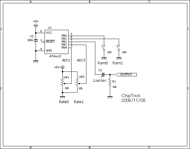
- ChipTrick schematic
- PCB design example
- parts list
-
Part# item memo U1 ATTINY13A 1 Chip CPU R1 10k carbon 1/4W C1 0.1uF ceramic 50V C2 10uF chemical 50V FRQ1 10K(B) FRQ2 10K(B) SW1 TackSwitch momentary type SW2 TackSwitch momentary type IC Sokect 8Pin DIP Jack φ6.3mm BatteryBox MU-3X2
- ATTiny13A including this kit had alreday have firmware inside. Brand-new ATTiny13A that you get need write software for yourself.
- Schematics and firmware may be changed without notice.
- PCB design example is single sided for home-brewed. this kit includes different version.
there also is all Japanese story about develop about this kit at "takedanote",Vol20,"Software Noise Generator"