MIDI-IF for Monotron Delay
Let's Mod MIDI-IF for Monotron to Delay

(Click to enlarge the picture.)
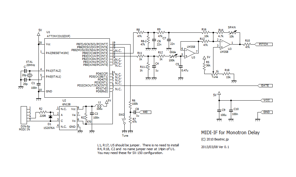
This is additional documentation for modding MIDI-IF for Monotron to Monotron Delay.
I've got some request for MIDI-IF for Monotron Delay.
I add some change to MIDI=IF for Monotron and adapt it to Delay.
At first. Monotron Delay has no octave span trimmer. I want to get not only FX sounds but also playable tune.
If you want to get some FX sounds then you should better to use ribbon, I think.
MIDI MOD may be more useful when you play notes. So, I add span trimer.
And Monotron Delay also has no tune knob. so I add it.
Monotron Delay has playable ribbon, and it's has keyboard picture. Monotron Delay plays 5 octarve by one octave keyboard mark.
so I found that MIDI-IF for Monotron needs some modification to adapt to Delay.
adding tuning knob method is based on the mothods that I develop for SX-150 version.
- Schematics for MIDI-IF for Monotron Delay (PNG format)
Adding mod onto Monotron Delay
(Click to enlarge the picture.)
It's based on MIDI-IF for Monotoron. so please get basic information from instruction manual page for MIDI-IF for Monotron.
And this modification is just only analog part only. I use same CPU that has same software for MIDI-IF for Monotron.
so MIDI functions are same as MIDI-IF for Monotron. please check
Monotron Delay has so wide frequency range. just one flick of ribbon can get over 5 octave of frequency sweep. That's the charm of this gear.
In normal Monotron, I had recommended that more easy method. But for Delay, I want you to try add transistor methods. Don't kill the ribbon.
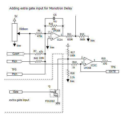
Adding transistor methods it based on Mr. Masa921 developed when the normal Monotron had been released. in this case, it's almost same as his method. This is the schematic of extra gate input for Monotron Delay.
- Extra gate inpu for Monotron Delay(schematic)
This picture shows that where we add digital transistor. I use FJN3302 instead of the choice that Masa921 made. Because of it's already dis-continued. Any transistor that has base register can be used for there, I think.
but Japanese pin structure is more useful to put it into inside of small enclosure of Monotron. Check its pin strcture by following pages.
- Data sheet for FJN3302(PDF file at Fairchild)

(Click to enlarge the picture.)
Put down to flat face where notes its name of transistor to the LM324(Quad ope-amp) then most left pin (3) is base.
The 2nd pin is corrector. it gose 9 pin of LM324. 1st pin of FJN3302 gose to the grand. I use 11 pin of LM324.
base pin of transister is additional get input. just draw out the wire there.
Adding connector, you can make it removable. when you connect midi-if then you can drive Monotron Delay by MIDI.
Remove it then you can play it by build-in ribbon.
there is no need to make it removable when you do that by chip resistor methods. because remove the chip resistor called R14 will kill the ribbon.
so you can only drive Monotron by midi. but in this method, We can use MIDI and ribbon, both. you can use them both at a time if you don't mind that the pitch is pop up when you touch the ribbon controller.
(Click to enlarge the picture.)
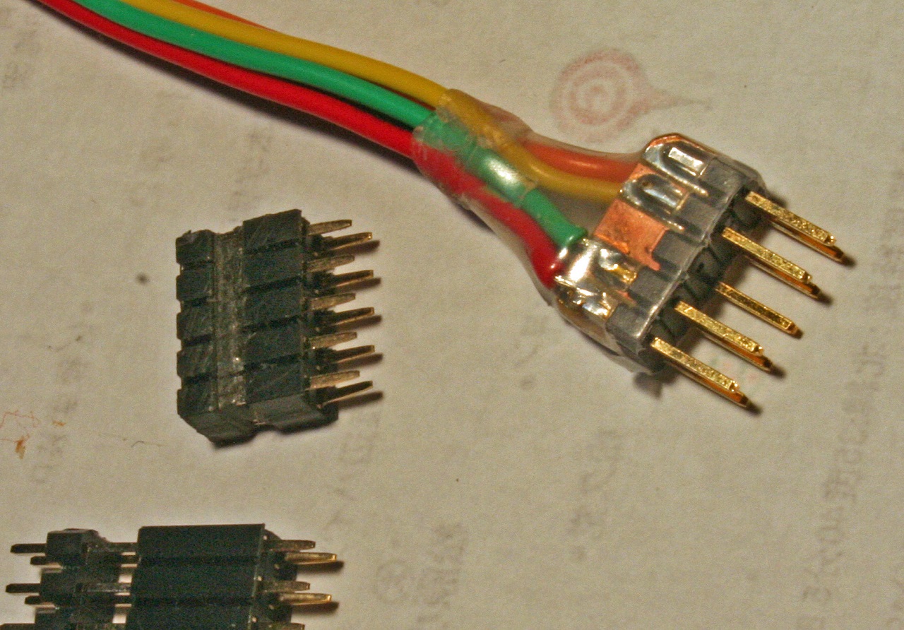
And there is one of issue what kind of connector we can use. Monotron series has no room inside of their enclosure. I use pin connector that's used by PC. it's small enough and cheap. but we need something additional ideas to fix it on to enclosure. my friend Msas921 also develop this methods. He dig a channel to hook up the slit. the slit is also need to dig for ourselves. next pictures may be your help
I still think that's not best solution. There should be more easy way to do that.
we may need something smaller connector to put. One of my customer use D-SUB9 Pin connector.
- Circuit Bending a Korg Monotron by The Native Transplants (At Facebook picture album)
The pin-out structure is free. Connect as you like. But when you are getting wonder how do this, check masa921's pin-out structure.
it's all Japanese page. use something translator service. but you may check the picture that shows his pinout structures.
Build MIDI-IF board
(Click to enlarge the picture)
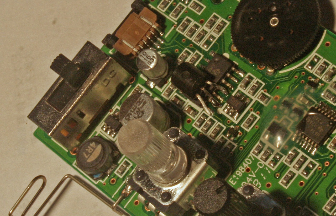
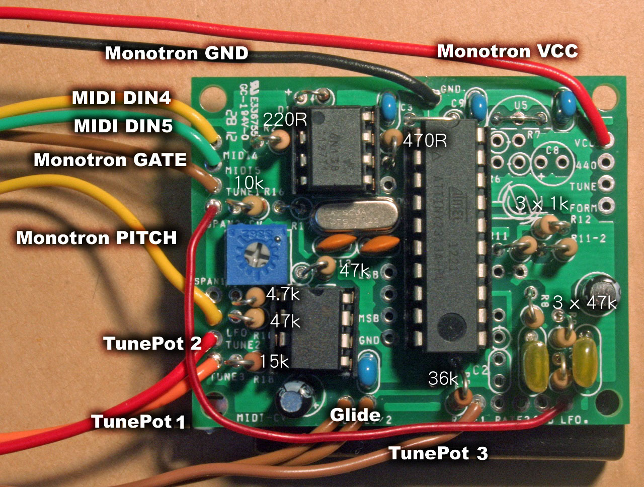
I mod my Monotron Delay. I get VCC, GND, Bias, Pitch and Cutoff from back side of Monotron Delay PCB that marked rand. I don't use gate out. gate is draw out from the base pin of digital transistor that you put
.
But in this issue, I use only VCC, GND, Bias, Pitch and Gate. I want to make the things more easy,
I used my kit "MIDI-IF for Monotron", And I add some mod to add octave span trimmer and pitch knob
.
This picture shows that values of registers only. Install Jumper line and capacitors as same as MIDI-IF for Monotron.
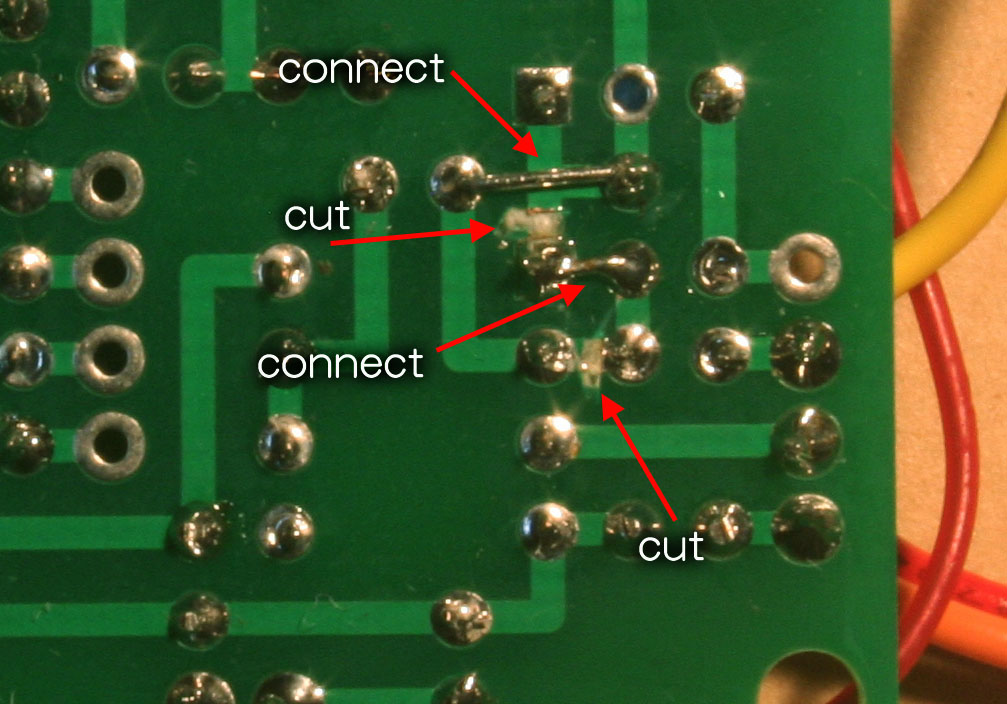
We need to add mod onto output buffer.
And you need to cut the trace of MIDI-IF's PCB. check this picure. Cutting the trace and changing the positions of registors and make it work as I need. it's just like jigsaw puzzle.
(Click to enlarge the picture)
In this configurations, you may loose the chance to use jumper line near at 14pin of U1. this jumper is switch the rate of vibrate by using hardware knob or MIDI-CC data. you install jumper then you may need add C2, R4 and R5 to control vibrate rate. But I use R5 for tune knob. anyway if you can add R5 outside of the board, then you still use this option. Anyway check schematic of MIDI-IF for SX-150 and study it.
And there is no attenuator for 220Hz for tune tone options. my video on youtube had got mistakes. around there. But you can use as is. when you build as same as video and you feel it's louder, then change R6 and R7. Check it y our own ears and change them as you like. In this configuration, you can still use this option to use 220Hz tuning tone. I strongly recommend to use this option. Monotron is not too tough for drifting of temperatures. Right tune makes you feel more alright!
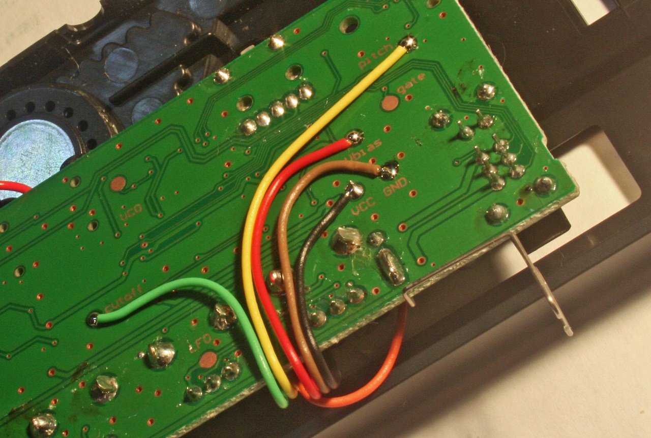
Get it wired and tuned
(Click to enlarge the picture.)
When you finish the board, check it closely. small chips of lead, or solder dust may be get you trouble.
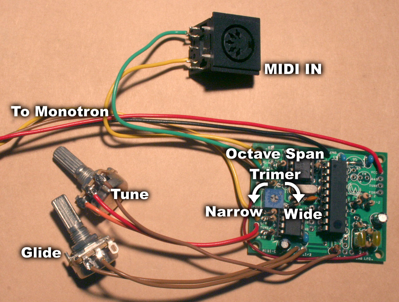
I use another kind of DIN connector that's different from my kit. it come from my junk box. Anyway may customer get mistake around here. Check DIN connector's pin-out here.
For wiring of glide pot, there is no directions on the board, but you should better to wire it as same as picture. 1, 2 pin should be used.
changing MIDI input channel option and changing wave shape of vibrate still can be used. please check this schematic and study it.
when you can get sound from MIDI, then tune it. tuning is most important part of synth works.
- 1. Play center C and turn tune knob as you like that easy to check its pitch.
- 2. Play one octave C. if its lower than you want, turn octave span trimmer right.
- 3. if its higher than you think, then turn trimmer left.
- 4. Then back to center C, you may hear another tune that you imagine.
- 5. This is normal thing.you change the octave span, so total tune is also changed. Back to the first step.