MIDI-IF KIT
Let's build your own MIDI-IF
This PCB is made for "MIDI-IF for SX-150" that comming from GAKKEN. But you can bend it for Monotron comming from KORG. When you use this board for monotron, you need mod on your monotron first. Please check it out.
When you want to get this board, please check Onlne Shop
I also shoot the video. Check it out! it may help your understandings.
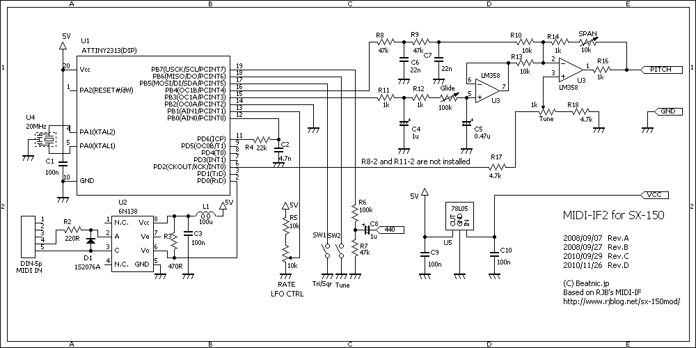
Schematics and bill of materials are here.
- Schematics(PNG format)
- Components layout
- Bill of material
This board have following functions.
- MIDI-CH for message receiving is fixed to 1. But you can change it using option. it's from 1 to 8.
- It receives MIDI note on / off messages.
- It receives pitch bend message. its width is fixed to 2 half tone.
- It receives modulation wheel message. Using this message, you can control the depth of vibrato.
- It receives control change message 4C (76 in decimal) as changing the speed of vibrato.
- Tuning support oscillator(440A)
- Power source is getting from Monotron.
At first
At first, we should add mod on Monotron. This mod will kill the Ribbon and enables the rand named 'GATE' at the solder side of the Monotron PCB.
This rand is connected to the pitch rand with resistor inside of the PCB. So, feeding the gate signal to the 'GATE' rand may affect not only gate but also its pitch. So we can't use the gate rand as is. this is the reason for removing chip resistor from the monotron.
Adding the solder to a chip registor that we attempte to remove, then
tip of soldering iron will grips it by the surface tension of molten solder.
there is no need to scrape or pull. You should better to try this way first. there needs some practice for beginners. Get controller board or so from broken hard drive or something. and remove some chip parts from it. there is no need to re-use the parts. you should remove it without damage for the board.
if you remove chip resister then you can play monotron from MIDI only. there is no need to rmove this boar from monotron.
but someone wants to build this board as removable by using connector or so, then they want to keep Ribbon alive. then we can use upper methods. We must add another gate input onto monotron. Or if you don't want to kill the Ribbon, then try this mod.
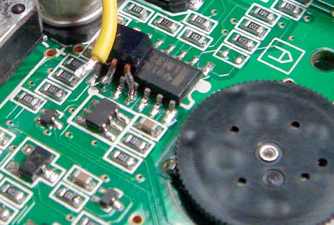
you should add TR inside of the monotron. it's just like
this. (the picture adding TR inside of monotron)
I use DTC114 as digital Transistor. It has resistor with base inside of it. In the picture, The yellow line come from base of the TR can be used as gate input instead of the rand at the solder side of Monotron PCB. In this case, we can use it as gate input, so there is no need to touch the rand of "gate" and there is also no need to remove chip register. And we can keep alive the ribbon.
My friend (masa921 SAN) write pages about this. it all Japanese page but you may check the schematics or so.
DTC114 is already discontinued . it's not easy to get here in Japan. But I found that "FJN3302" can be used instead of DTC114. Their pin stracture is Japanese fashions.
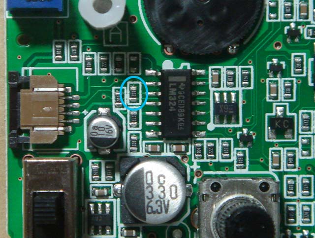
Put down to flat face where notes its name of transistor to the LM324(Quad opeamp) then most left pin (3) is base. in the picture, there is yellow line. the 2nd pin of FJN3302 is corrector. it gose 9 pin of LM324. 1st pin of FJN3302 gose to the grand. I use 11 pin of LM324.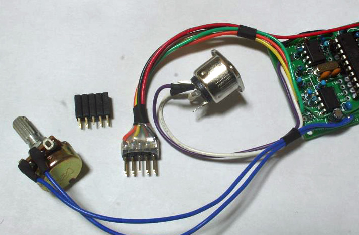
this is easy mod, compared to that in the monotron add a connector. there is no room to add something inside of monotron enclosure. you may need something more smaller connector to put into it. some of my customer use D-SUB9 Pin connector.
Circuit Bending a Korg Monotron(on Facebook ) by The Native Transplants
I use black small one that mother board of PC uses. and I dig slots on to the side of monotron enclosure. it so hard for me.
try to find more easy way to adding connectors for this, please.
The 1st Steps
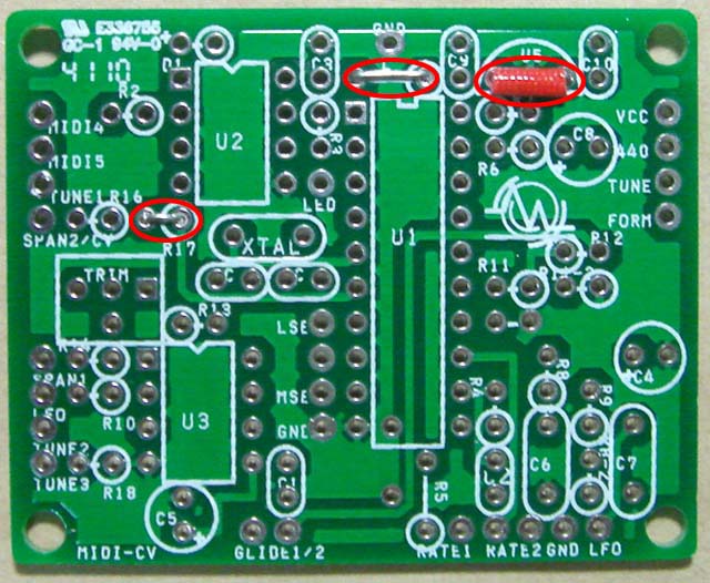
The theory to build a board, we must start lowest profile parts first. It should be jumper leads.
When you turn board over to solder them, the parts that you want to solder will fall off from the board. But if its height is the same, you can avoid falling off the parts from the board.
First, most lower profile part and then higher and higher.
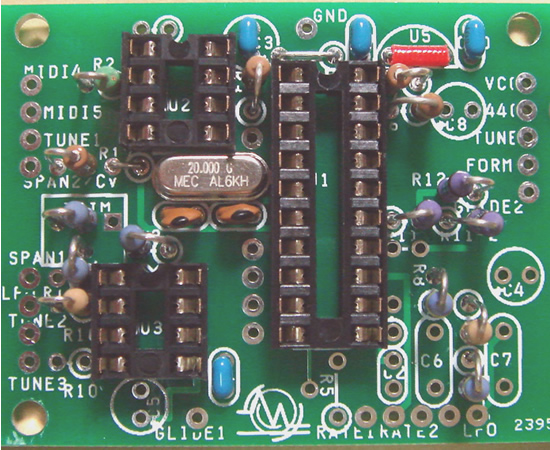
You can see the "L" mark in the middle of the board at higher position. You can install there some inductor. When the noise that is coming from Photo-coupler make you trouble, Install inductor there. (it should be 100uH or so.) But there is no needs to use it usually. Just jumper leads is enough.
In Monotron configration, our power source is getting from monotron and there is no need for local regulator. So, we have no need install U5. But the rand in the middlle of 3 terminal regulators is GND. Be careful to not to touch the jumper line to the GND rand. I put the red tube around it.
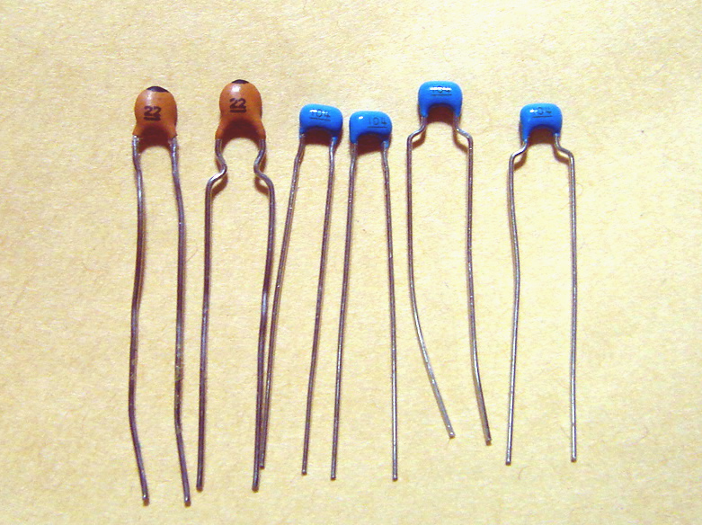
The 2nd steps
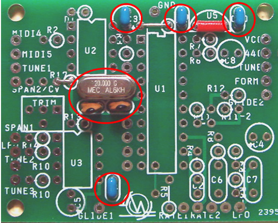
Let's install small capacitors. At first, if lead of yours are bended you should better reform it to fit this PCB. Just do it like this. (the picture for bending lead to fit the PCB)
I use small package of xtal. please check that not to touch the case of xtal to sockets or so.
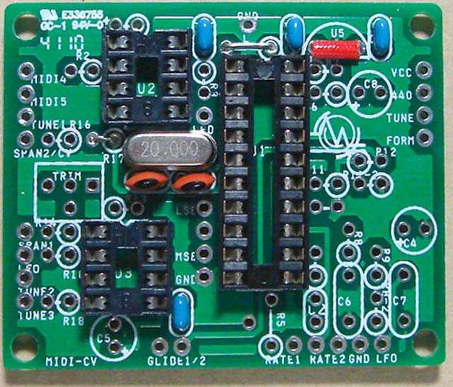
the picture after installing sockets are here (Picture of sockets)
when you solder a sockets for IC onto the PCB, solder 2 diagonal pin, first.next, turn around PCB and check the direction and
horizontal flatness on the board. if it OK sorder all the rest of the pins.
The 3rd steps
All the resistor of this PCB is standing position. Bend the lead of you resistor from top position of color code to make easy to check its value after soldering.
Put the resistor onto the board and spread its lead not to falling down. Then solder only one lead first.
next, turn over PCB and check the position and attitude. is it OK? Then solder rest of the lead. and cut them out the leads.
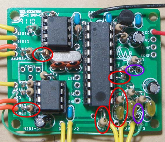
There is 2 way of configurations. it will be changed by installing resistors round the opamp. This picture is for Monotron.
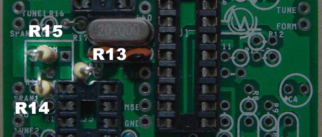
You should put R14 in defferent way from the silk print on the PCB. R14 use the hole for trim pot.
And You may found the R15 in schematic but there is no silk on PCB. We put R15 on hole for trim pot.
This changes, make right way for schematics.
Pitch cv will output through 10k for VCO and 100k for VCF. Check the picture closely.
The last steps

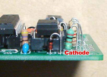
This picture is Monotron configuration.
The rest of the parts are diode around the photo-coupler(U1) and capacitors. Chemical capacitors have polarity. And they are not so strong for the heat of soldering irons. Check them closely but solder them quickly.
About diode, bend the cathode side of lead and install displayed by picture way.
In the schematic or BOM said that R2 is 220Ω but we can also use 200Ω. Some LOT of my kit include 200Ω use it instead of 220Ω
Don't forget the long jumper line from LFO out to LFO in.
In Monotron configuration, there is no need to tune on this board. There is trim pot on monotron PCB. but monotron PCB has it for tune. You can trim 'octave span" by that. This issue is should be written in later sections.
you may found the rand named "tune" and "440" on right side of the board. This is tune support functions. Connect "440" to audio amp and get down "tune" to the GND. You may get 220Hz sounds from amp. It's the same tone that getting from Tuner machine for guitar or so. in this mode, CPU pretend that get MIDI node #53, put the CV for A and up the gate. you trun Tune knob on monotron and tune it.
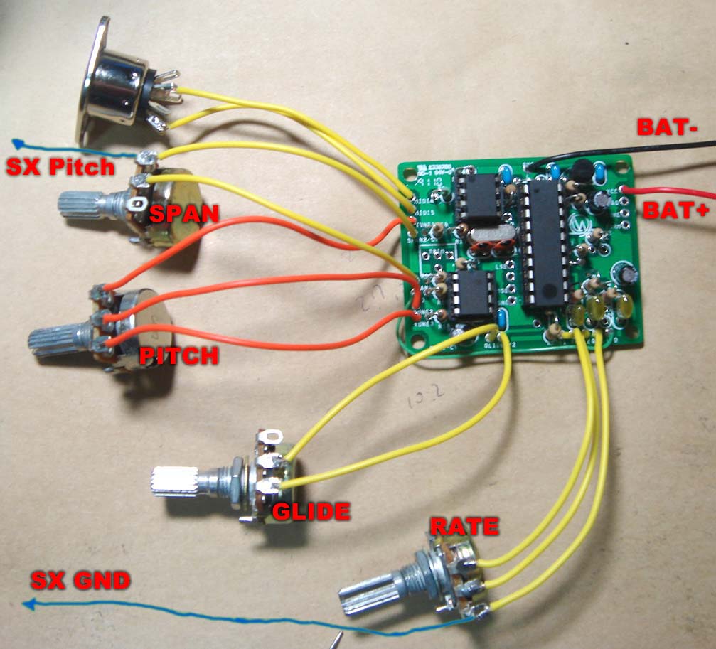
Get it wired
when you finish the board, check it closely. Especially in Monotron configuration, The power line is connected monotron directly. If there is short circuit on it, monotron may get big damage. Monotron have DC/DC converter inside. And there is no guard for short circuit. When you done it, it's not easy to fix.You may need to get another one.But it should be a big chance to learn more inside of monotron. Try anything, there is nothing to fear.
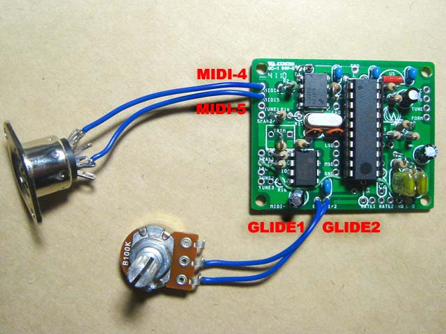
There is 2 set of cables that not connect with monotron.
one is for MIDI connector and the other is for "GLIDE". If you don't need GLIDE function, then just only short them directly.
The picture shows that the 3rd pin of GLIDE pot is open. But the best way is short it with 2nd pin.
Almost all the trouble is connection of MIDI-Connector. Check its pin scructure and positions carefully.
Connect with Monotron
This board is orignaly designed for SX-150. And we use it as monotron configrations.
So the pirnted silk is just little change from monotorons.
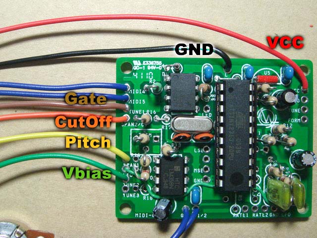
This picture shows rand name of monotron's PCB. Draw out 6 lines from MIDI-IF and get connect them on monotron.
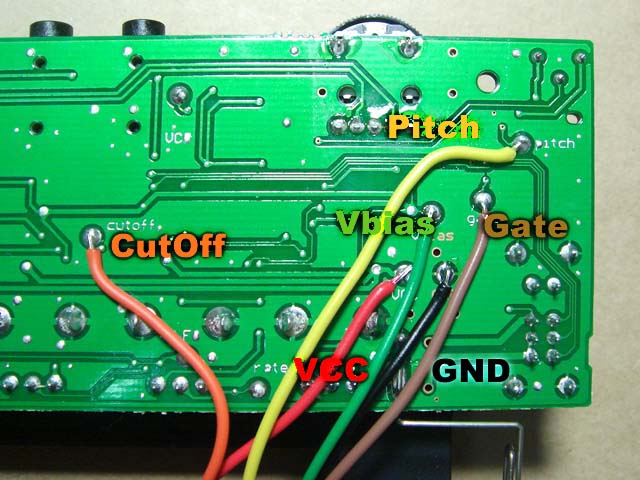
for taking pictures, I use just little fat cables to make it more clearly. but it too fat. we should better use more slim cables just lile flat cables or so.
The rand on the monotron is so small try them not to short or bridge or something . check it out also pictures.
Tune it
Connect all the cabele to get sound from monotron, incuding MIDI-cabel. Then you may hear the sound from monotron when you play keyboards. Tune it easy frequency and play 2 different note by one octave alternately.
if it not reach an octave then you should turn trim pod in the motron clockwise. if it over an octave then turn it anti-clockwise.
It's not easy to tune Monotron++ correctly. But never mind. Monotron has no temperature compensation. it's always drifting like guitars or alto sax or so.
Drifting is one of the charm of Analog synth. never mind. Welcome to Analog Synth World!
Optional functions for MIDI-IF for monotron
| MIDI CH | 1 | 2 | 3 | 4 | 5 | 6 | 7 | 8 |
| 7Pin(LSB) | 0 | 1 | 0 | 1 | 0 | 1 | 0 | 1 |
| 8Pin | 0 | 0 | 1 | 1 | 0 | 0 | 1 | 1 |
| 9Pin(MSB) | 0 | 0 | 0 | 0 | 1 | 1 | 1 | 1 |
MIDI-IF for monotron has some functions. Check the schematic and choose whay you needs and add it.
- schematic for option function(PNG format)
MIDI-CH can be changed from 1 to 8. Connect PIN 7 to 9pin to dip switch or something and set them as follow. 1 means down to GND and 0 is just open. all the pins are pulled up by CPU inside. all open is default and it means ch1.
FOR SX-150
If you want to build this board as for SX-150, then you need more parts to install.The schematic for SX-150 configuration and BOM is follow.
the defference of Monotron and SX-150 is ..
- Adding 3 terminal regurator for battery drive
- You can change LFO rate for vibrate by knobs
- Adding octarve span knob as SX-150 dose not have it
- Adding tune knob
- Adding LFO wave shape selector(SWQ/TRI)
We need jumper line near by the 14pin of ATTiny2313, adding R17(1K), R18(1K), R4(22k), R5(10k), C3(0.0047uF) and removeing R8-2, R11-2.
the position of R14 is the same way of silk print. it's 1k. check the picture of the board.
There is no room for the knob for LFO rate. I did it by MIDI controle change message. This function can be changed by jumper line near by 14pin of ATTiny2313. you put switch instead of jumper line, then you can switch knob and MIDI both.
Jumper line around 14pin of ATTiny2313 is the switch. you short this then you can use knob for speed, or not you can set the speed by MIDI controle changes. you can replace it to switch instead of jumper line. you can switch both functions.
LFO wave form switch is most easy mod for this board. try yourself.
And you can also use this function for Monotron confoiguration.
for more information, Please check following page.
More Mod
Adding another hack onto SX-150 configuration make it enable to be used for general use MIDI-IF. Ceck following page.