CountBeats jr Kit
Let's Count the beats

This project is designed for beginners for electricity. it's called 'Count Beats jr'.
At first, I intend it as a 'Metronome'. You can use it when it's too loud to hear the sound of Metronome for practice of percussion ensemble or something.
Or when it's too silent to use the metronome for recording of strings ensemble or so. Flashing lights will guide you a right beats.
And this gadget have not only flash but also decay of the lights. You can feel the back beat of the tempo.
Any way you should better think that it's a metronome without sound . It's just lights only.
You may feel that it's stable enough, but there is little drifting that caused by temperature changes. you can't trust this too much.
But if it's just practicing, then there is no problems. There should be another version for professional. The name of this kit also give a hint about it.
And I realized that when I finish build the very first version of 'Count beats', seeing flash light brings me to another stage in my mind.
You may use this not only musical use, but also for another tool.
There is 8 LEDs and 15 components. it's not too much. it's may be good for the beginners. It will take 20 minutes to finish to assemble.
There is no triming point for tune. You don't need measuring instrument or oscilloscope.
But if you are thinking to continue this kind of things that even it's just a one of your hobby, you should better to get digital multi-meter for the first.
Anyway this is designed as "just build it, then it works fine".
You can use this as stand alone with battery.
this kit is just only PCB. you may need enclosure. And this has no power switch. Get off your batteries when you don't use this.
Put this board into your orginal box, take its picture and send it to me to share the idea of yours with the worlds.
You can also use this kit just as a part of your another project. there is some option function. in this kit, I will write about it in later.
All the schematics and BOM are at the last of this page. please check them out also later.
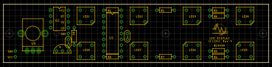
check the compornents out!
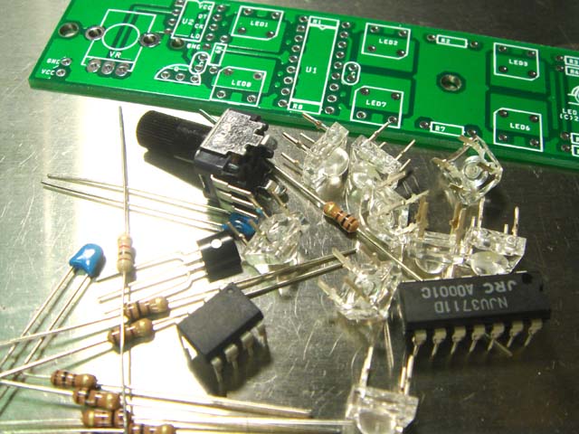
Main component is one chip CPU. It gets 9.6MHz clock its inside and counts it for serial to parallel converter called NJU3711. Anyway ATTINY13A is too small to light the 8 LEDs so we need this chip there. this chip can't get much current for LEDs.
NJU3711 determines what LED lights. And It's brightness is controlled by transistor with PWM signal from CPU.
Don't forget the LEDs. When I start this project, I planed to use xenon lamp for flash light for photographic use. But I found that FLUX type LED has enough brightness. This LED makes this project more easy to build.
This kit uses 2 kind of resistors. they have 4 stripe on it. the first one means 1K Ω(Brown, Black, Red, Gold). We use it just one for this kit. And the other means 100 Ω(Brown, Black, Brown, Gold) , And it works as current limiter for LEDs. We use 8 of 100 Ω
We can change the max brightness of LED by changing the value of 100Ω.
In this design, NPN transistor works as changing brightness of LED as dynamically by PWM signal from CPU.
Small blue capacitor works as de-coupling capacitor. they removes the noise coming from power line. We can read some numbers on it. And it may be "104". This numbers means 0.1μF. We use "u" instead of "μ" to make explain easy.
Let's get start to soldering
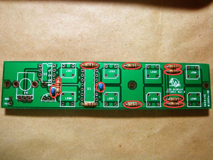
There is 3 steps for the process to assemble. The first is resistors and capacitors. next, it's LEDs and IC, then POT and Transistor.
I decide it by the height of parts. if capacitor is electrolytic type and more higher than IC, then you should better solder it after IC.
When you place the PCB upside down on the table to solder the parts that you installed on it, some of them are getting down on the table.
Its heights are not aligned. you should better set them as same hieght for same kind of parts. I think that's the point
But if you put correct parts on correct place then it would work correctly. Never mind, Any style can be OK for the beginners, if it work fine. When you become more familiar with that, let's get correct style.
Steady style may help you, when it don't work as you think.

Solder may melt quickly when it touch to the soldering iron. We should put the heat onto the rand that the doughnut around the hole and the legs of components, first. Then add solder onto them. Putting heats is just a second and put solder next a second. Total time may be 2 second or so.
Too much heat may get damage onto components.
Semiconductor such as IC's or LEDs has the polarity. You check it direction carefully. IC has 1pin mark on it. some semiconductor has just only white dot or another on has engraved mark.
Upper line and lower line of LED has different directions in this kit. for upper line, cutouted mark should be under right side, and lower line should be upper upeer left side.
all the pictures on this page can enlearge by clicking. check them closely.

Transistor also has polarity. Check its directions. About pot, you must solder not only 3 leads but also 2 legs to fix its body to the board.
I painted white slit on the shaft of pot to make it easy to check its position. I used tooth pick made by wood to paint it. Get the paint on the tip on it and touch the slit then it flows themselves.
After dry enough, I scrape off over paint by design knife or so.
All the parts are installed onto the PCB, then solder battery box or battery snap.VCC means +line. GND is -line (it may be black).
Add power switch if you want.
This project may work by 2 AA batteries, but it not enough to flash the LED. you should better use 3 AA batteris as 4.5V. if you want to drive it by AC adapter, you must use regulated 5V type.
some of easy type has no regulator on it and the voltage comming from AC adaptor may up to 6-9V. This voltage will burn the CPU. MAX voltage for CPU is 5.5V.
check it out, please.
Finished

This kit includes no enclosure. So this picture is the goal of this project.
The picture at the top of this page shows my original encosure. It's made from white acrylic board, aluminum channel and 2 pieces of woods. I put AC adaptor connector on it.
I can't put batteries in it. Some re-chagable batteies may be small enough put into the encosure or so.
Just you plug the batteies or AC adaptor, then it will start to work. Upper line will count quater note. under line will count the bar.
2nd pin of Tiny13A get chnge of Voltage from 0V to VCC. (it's means same voltage that CPU will gets).
Using panel type pot and not to install it on to the board will make it more easy to arrange for some enclosure.
What kind of? I want to see your ideas. Please show me yours!
Small option
Have you ever heard about "Monotribe"? It's Korg's affordable groovie machine. check it out. It has 16 step sequencer, full analog drum sound source and Monotorn.
And it have also "Sync" input and output. it's get sync with another equipuments.
"Count beat jr" has "sync out" for monotribe by option. Connect your "Count Beat jr" with "Monotribe". You can controle its groove by "Count Beats jr".
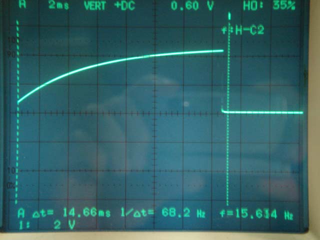
The 3rd pin of ATtiny13A outputs 16 trigger per bar. And its plsue width is 15ms. You need add some more to sync with monotribe correctly.
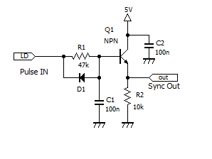
The schematic for wave shaper for monotrbe is just like this.
| Part# | item | memo |
| Q1 | Any NPN Transistor | 2SC1815 or so |
| D1 | Any Switching Diode | |
| R1 | 47k | carbon 1/4W |
| R2 | 10k | carbon 1/4W |
| C1 | 0.1uF | ceramic 50V |
| C2 | 0.1uF | ceramic 50V |
This schematic works as this picture. The fast edge of trigger is made more soft by this scheme. You can change the curve by changing R1.
This curve is optimized for sync signal of monotribe and 15ms puls width.
It's small enough, so you can build this on the bread board.
You can use this schematic for Arduino or some other platform to make it sync with monotribe. Make sure that pulse width of trigger should be 15ms.
parts are listed here. You can use any transistor. Diode should be fast switching type.
Documents
| Part# | item | memo |
| U1 | NJU3711D | LED Driver |
| U2 | ATTINY13A | 1 Chip CPU |
| Q | 2SC1815 | NPN Type |
| LED1-8 | OSW75LZ161D | 7.6mm FLUX Type |
| R1-8 | 100 | carbon 1/4W |
| R9 | 1k | carbon 1/4W |
| C1 | 0.1uF | ceramic 50V |
| C2 | 0.1uF | ceramic 50V |
| VR | 10K(B) | |
| BatteryBox | MU-3X3 |
I provide "CountBeats jr" as kit. But you can build it with this information.
ATTiny13A including this kit had alreday have firmware inside. Brand-new ATTiny13A that you get should need write software yourself.
Schematics and firmware may be changed without notice.