

Modify your Monotron, ADD CV + GATE
Get the schematics first!
It had got to be big topic that there is the mark that what kind of signals comes around when monotron had been released.
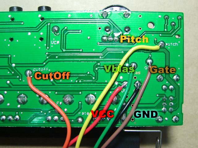
Let’s check next 6 lines. it’s VCC, GND, GATE, Bias, Pitch and CutOff. What kind of signal we can get from there? let’s get check it out there.
Korg had published the schematic of Monotron and anyone can download it. Follow next link and get it.
you can find “Download” button at the bottom of the page. Let’s get check the schematics.
off couse you may loose your warnnary if you remove the back panel of monotron. Do it with your own risk.
上記ページの一番下に、「Download」のボタンがあります。回路図を見ながら、信号を見て行きましょう。
(もちろん、monotronnの裏蓋を開けてしまうと、メーカーの保証は受けられなくなります。自己責任でトライください)
What kind of signals we can get?
- VCC
- GND
this is the same voltage of spring of batteries. the value of VCC is difference from here.
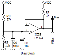
- Bias
For driving Opamp, we need bias voltage. And this voltage also output from monotron to outside. this line is bfferd by IC2B. R10 and R9(each of them are 27kand10k) divide VCC, and it’s 1.35V or so.
Monotron use LM324 as Opamps. It’s single rail type. Normal Opamp needs the margine from power line. this opamp also needs margine to VCC. but lower side is around 0V. so you can use around 0V up to 4V or so in 5V operation.
Bias voltage is just little lower than the center of the vltage that we can use. suppose why it should be. that the oen of fun of analog schematics!
- GND
電池のマイナス(ばねの電極)と同じ電位が取り出せます。VCCの電圧は、このGNDポイントからの電位差です。
- Bias
Monotron内部でオペアンプを使うための基準電圧が外部へも出力されています。IC2Bを使ってバッファリングされています。電圧は、R10とR9(それぞれ、27kと10k)で分圧されて、1.35Vぐらいが出力されています。Monotronで使われているオペアンプは、LM324というもので、単電源タイプです。一般のオペアンプでは、電源圧から上下ともに数ボルトのマージンが必要ですが、単電源のオペアンプ優れているのは、一般のオペアンプと同様上限には、マージンが必要ですが、下側についてはほぼ全部の電圧範囲を使えることです。この回路の中で使われている、LM324の電源は、DCDCコンバーターで昇圧された0Vから、5Vですから、このオペアンプが扱える電圧の下限は0V、上限はVCC電圧の5Vから、オペアンプの動作のマージンを差し引いた4V弱程度になります。さらに、回路の動作として、上へはみ出すマージンを考えて、回路全体の動作の基準点として、本来取れるはずの2V付近よりちょっと低めの電圧に設定されているのではないかと思います。この辺がアナログ回路のダイゴミかもしれません。
- GATE
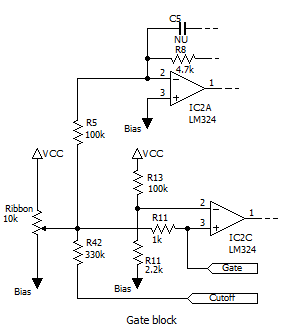
In the schematic that I trace from original, the Ribbon is seems to be a retio-stat. Actually when you touch it, it’s as is. And when you don’t touch it, the sweeper is not touch anything.
But there is bias voltage thorough R5 from – input of IC2A. + input of IC2A gose to bias, so there should be bias level because of vertual short.
In the other hand, the – input terminal of IC2C as compalator gets the voltage that divided from bias to VCC by R13(100k)and R14(2.2k). it should be just a little bit but surely upper than bias level.
Each end of ribbon is coverd by the enclosure, so when you touch the ribbon you get the voltage upper than bias.
you can use this page instead of hit the DENTAKU key when you want to get divided voltage from 2 registors.
http://www.aleph.co.jp/~takeda/radio/calc.swf
押されていない間、摺動子は、どこにもコンタクトしていない状態になっています。
ただ、ここには、別途、IC2Aで構成される反転アンプの入力端子がR5を経由して接続されており、この反転アンプのもう一方の入力端子は、バイアスに接続されており、2つの入力間はバーチャルショートとなるので、リボンが押されていない時には、ゲートを生成するIC2Cの+入力はバイアス電位が掛かります。
一方、IC2Cの-入力端子は、バイアス電位とVCCを、R13(100k)とR14(2.2k)で分圧した、ほんのちょっと、だけど確実にバイアスよりは高い電位が入力されており、(コンパレーターの+/-の入力の電位が反転しているので)OFFになります。
実際は、VCCから、バイアス電位を引いた値(5V-1.35V=)3.65Vを100kと2.2kで分圧した電位、0.07Vぐらいバイアスより高い電位になっています。
抵抗による分圧の電位、電卓をたたく代わりにこちらのページが便利です。
http://www.aleph.co.jp/~takeda/radio/calc.swf
リボンの両端は、ケースにカバーされており、ぎりぎりのところはタッチできません。タッチで確実に、バイアスより0.07V 高い電圧がでますので、コンパレーターが動き、LFOにシンクを掛けるます。
- Pitch
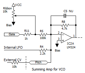
Single Supply Op Amps that’s used for monotron can get around 0V by single power source. it’s is great. But there is also small weak point.
there is distortion point around 0V (or bias). because of the switching output stage around it. it’s called as zero closs distortion.
The R7 at the output of bias block bleed current to shift the point of distortion.
there is same technic is used for R73 at last stage of VCF. in this case, it’s got down to the ground. That’s one of basic technic for using affordable chips.
単電源オペアンプは、0Vぐらいが出せるという、優れた性能だけでなく、残念なポイントもあります。オペアンプの出力段で、0V付近(バイアス電位)周辺で、その上下で出力段の切り替えがおき、意図しない歪が発生します。一般には「ゼロクロス歪」といいます。ここでは出力をむりやり上に引っ張りあげる(無駄に電流を流す)ことによってその歪が発生する個所を違うところにずらしています。
同様の処理をVCFの最終段でR73がやっています。こちらは、下に無理やり引っ張っています。安価なオペアンプを上手に使いこなす必須のテクニックです。
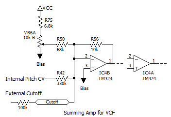
- CutOff
Add external gate input
- Pitch CV though registor that you add to there
- Gate voltage through R11
ゲートが入るときには同時にPitchにもCVがかかってるはずで、VC0のサミングアンプは、下記2つの電圧の合計で VCOを動かすことになります。
- Pitchのテストポイントに追加する抵抗経由の電圧
- R11越しに入力されるゲート信号の電圧
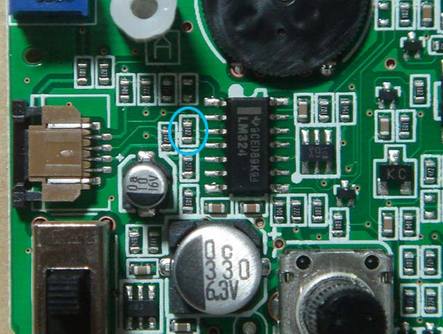
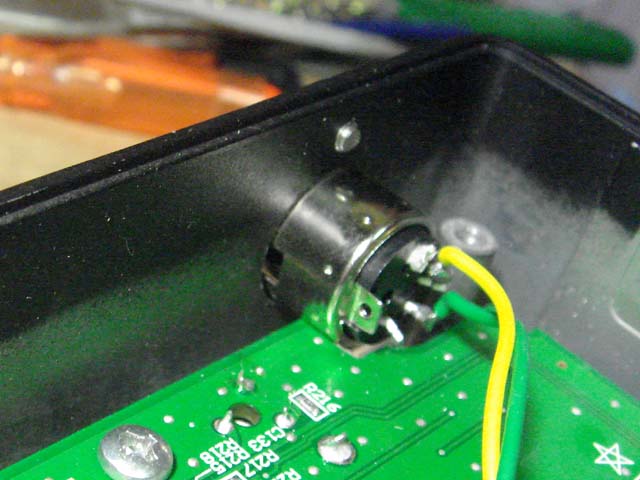
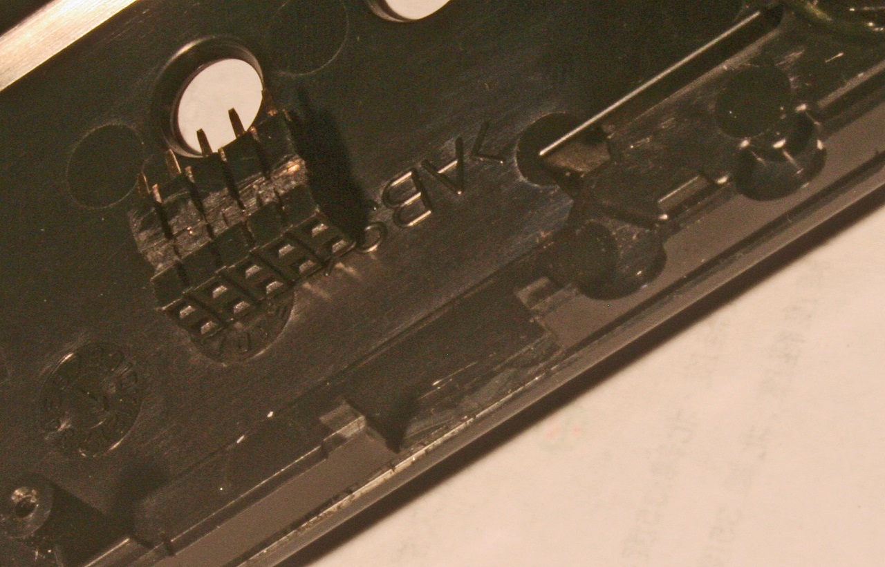
most simple way to remove the affect of gate voltage to the pitch is removing R11.this methods cut the path to make pitch and gate singnal inside of monotron. Blue circle is the R11 on the picture.
Removing Chip registor from PCB is not easy for everyone.
Adding the solder to a chip registor that we attempte to remove. make registor floating in molten solder then tip of soldering iron will grips it by the surface tension of molten solder. there is no need to scrape or pull. You should better to try this way first. there needs some practice for beginners. there is no need to re-use the parts. you should remove it without damage for the board.
this mod allow you to add gate signal without any affect of gate signal level or something. but it kill the ribbon. Monotron should be getting not to be able to get sound itself. Your need gate signal from outside.
if you no need to touch to the ribbon, then this mod is simple and easy.
たとえば、外部のMIDI-CVコンバーターから、Pitchの電圧を受けて、正確なピッチが欲しいような場合には、微妙なピッチのずれがあると、アンサンブルの中でメロディーを演奏できません。他に、悪影響を与えずに、ゲートを掛ける方法を考えます。
シンプルバージョンとしては、とりあえずR11をはずしてしまい、ピッチCVの発生とゲートの発生とは違う経路に分断してしまう手があります。写真に青い枠でマークされた抵抗が、モノトロンならR11になります 。
チップ部品を基板からはずすのは、狭くて小さくて大変です。ハンダ吸い取り線などで、はんだを吸い取ってしまうのではなく、むしろ逆に、はんだを追加で盛ってしまい、溶けた半田の中で部品が泳ぐような状態にします。そして表面張力で盛ったハンダ丸ごと取り出す感じが良いかもしれません。無理にゴシゴシやるとほかのトレースをき傷付けてしまうことがあります。はずしたチップ部品にはほとんど使い道がありません。むしろ基板を傷つけないようにしてください
この改造によって、裏のゲートのマークの付いたランドから他に影響を与えないようにしてGATE信号を入れることが出来るようになりますが、同時に、Monotron本体のリボンをタッチすることで演奏できなくなります。たとえば、MIDI-IF等をつけて、限定的にそれだで発声させることができればいいのであれば、このシンプルな改造はお勧めです。
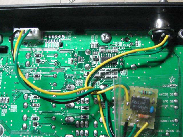
by using this methods, marks on the back side of the PCB is as is.
but the line “pitch” and “cutoff” is conected on invert input pin of opeamp directly.
this point has so high impedance. So you should better to not to draw the line too much. you may get noise around there.
VCC, GND and Bias lines are power source. you can feed power to something you connect outside of monotron.
but controlle cv inputs are just Gate, Pitch, Cutoff and GND. you may be able to use 3.5mm mini jack in monotron enclosure. anyway to find the room to put the connector is another difficulty for this DIY.
特に、PitchとCutOffのラインはオペアンプの反転入力に直結なのでとてもインピーダンスが高くなっています。長く引き回すとノイズが載る可能性がふえます。できるなら、あまり伸ばさないほうが良いです。
VCC、GND、Biasは、電源関係です。外部に接続するかもしれないアイテムに、電源を供給するために引き出しています。
シンセとしてコントロールに使う信号線は、Gate、Pitch、Cutoff、それから、その電位の基準点になる、GNDの4本です。
モノトロンはそのものがちいさいので、本体に、これらの信号を出すためのコネクタをつけるのがむずかしいかもしれません。電源は別でとることにして、コントロールだけ出すつもりであれば、3.5mmミニジャックに4極のものがあります。コネクタの種類を選べば、本体内に収めるスペースがあるかもしれません。
We need to do some other methods, when Adding MIDI-IF, then you can drive monotron from MIDI. but removing it from monotron, then you can’t get sound monotron itself.
this methods kill the ribbon.
たとえば、コネクタなどで接続できるMIDI-IFを後から追加して、MIDIから、演奏が出来る。さらに、IF無しならこれまでどおり、本体のみでも演奏出来るという仕様にするなら、この改造は、リボンを殺してしまうことになるので、他の方法を考えなければいけません。
Don’t kill the ribbon!
Adding transistor methods it based on Mr. masa921 developed when the normal Monotron had been released. the methods that indrduce to you here is almost same as his did.
His Original page is here
the provider site that he use not allow to access from some of over sea. I can’t believe that!.
Monotron Delayのリボンコントローラーは、Monotoronにくらべてとても広い周波数レンジが設定されています。1フリックで、5オクターブぐらいスイープすることが出来ます。とても魅力的な機能です。Monotronでは、簡単な方法でゲートを追加することをお勧めしますが、MonotronDelayでは、トランジスタの追加メソッドをお勧めします。ドントキルザリボン!(YesのDon’t Kill the Whaleを思い出してください、いや、深い意味はないですが)
トランジスタの追加メソッドは、normal Monotronがリリースされた当時に、masa921さんが開発されました。ここで紹介するメソッドは、氏が開発したものと一緒です。氏のページはこちらです。
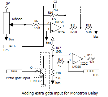
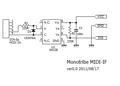
This is the schematic of extra gate input for Monotron Delay.
The key of this method is .. by shorting R18 by added TR, get down the compare voltage low to make compalator on instead of getting ribbon voltage high.
masa921 use DTC114 but it’s already discontinued item and it’s not easy to get now. so i use FJN3302 as another choice of digital TR.
MonotronとMonotronDelayは、VCOまわりにかぎれば、部品番号など若干違いますが、ほとんど一緒です。このメソッドはもともと、Monotron用に開発されたのですが、MonotronDelayにもそのまま使えます。
回路図は、トランジスタを追加して、リボンによる演奏機能も残すゲート追加のための回路です。
味噌は、比較のために用意した電圧よりリボンから来る電圧が上がるかどうかでゲートを出力するのではなく、用意したはずの電圧を下げてしまい、リボンが押されたも同然に見せるといというところです。回路図のR18をトランジスタでショートすることで比較のための電圧を0Vに下げてしまうという方法です。
masa921さんはDTC114というデジトラを使われましたが、入手しにくくなってしまったのでこちらでは、FJN3302を使います
the reason to use Digital TR is only the space. if you have enough room to put parts then you can use simple tr and base registors.
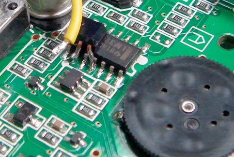
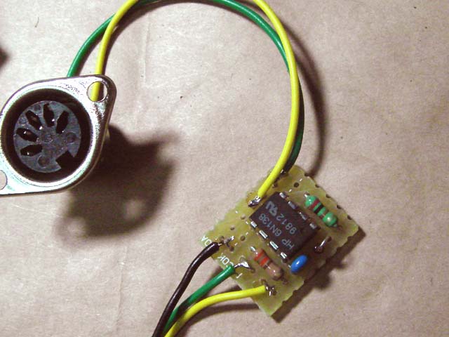
Put down to flat face where notes its name of transistor to the LM324(Quad ope-amp) then most left pin (3) is base. it’s just in the air. it don’t connect anywhere on the PCB.
The 2nd pin is corrector. it gose 9 pin of LM324.
The last pin of FJN3302 gose to the grand. I use 11 pin of LM324.
base pin of transister is just in the air. When you finished to check if it works or not, glue the IC and the transistor together, as soon as possible. It’s so easy to tear off around there by pulling wire of the base.
you can this lead as additional get input. just draw out the wire there.
this drawings may be help for you, also.
デジトラを使う理由は単純にスペースの問題です。もしベース抵抗を入れるスペースがあるのなら普通のトランジスタを使っても問題はありません。
トランジスタ型番が表記されているの平面をLM324 に押し付けて、一番左の足がベースです。これは中空配線します。ドコにもショートしないようにしておきます。
真ん中の足がコレクタ。LM324の9Pinにハンダづけします。
最後のエミッタは、LM324の11番ピン、グランドに接続します。
何かの拍子で中空配線したベースピンが引っ張られたりすると、トランジスタはモチロン、基板上のトレース丸ごとむしれます。動作チェックが終わったらグルーガンなどで、トランジスタとオペアンプを固定しておきます。
これで、外部入力ゲート端子が追加できました。下記の図面も参考になるかもしれません。
- Adding extra gate for monotron(hand drawings for adding extra gate)

this methods based on for monotron, so you can use this for monotron also.
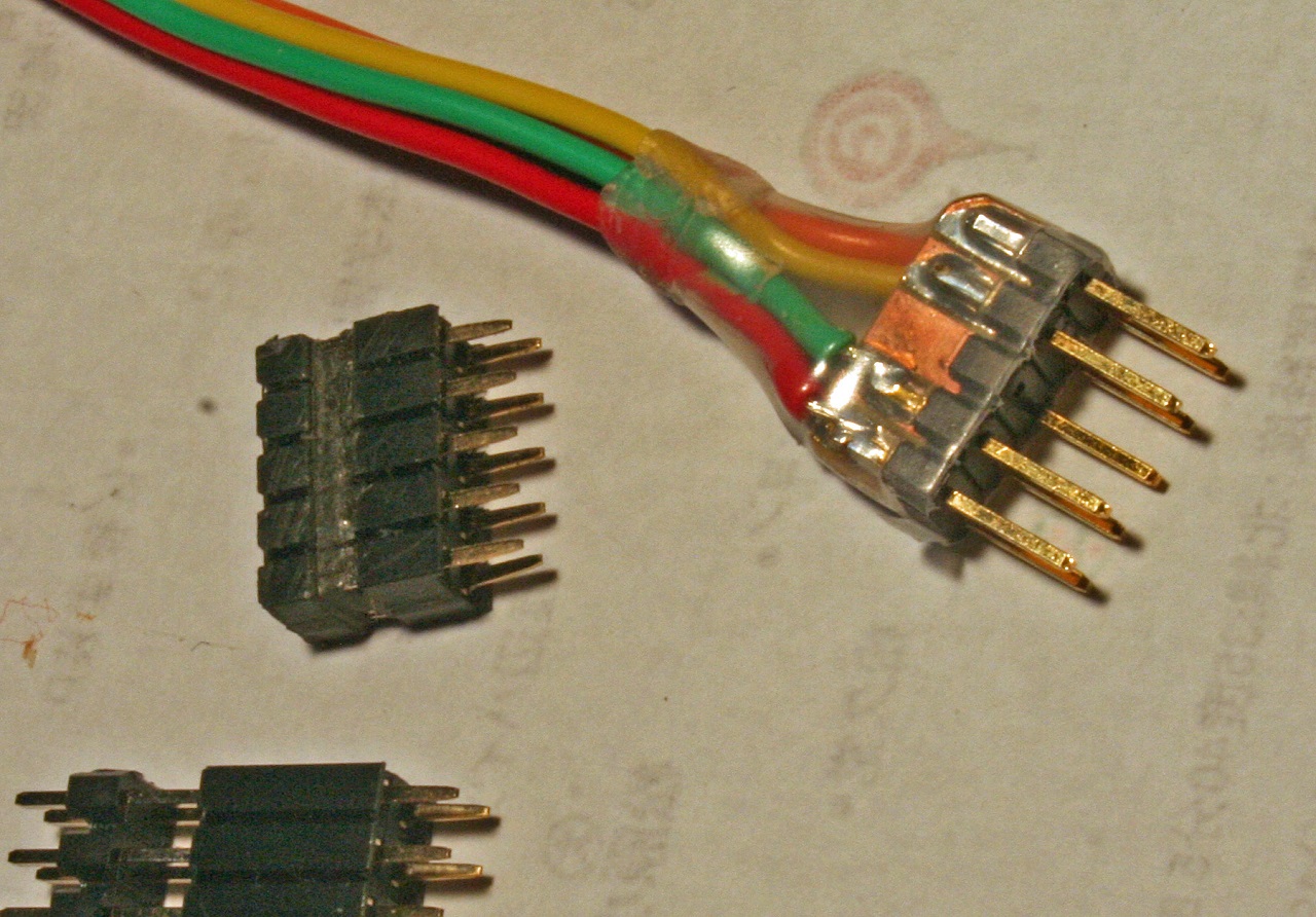
Adding connector, you can make it removable monotron and another equipments. When you connect MIDI-IF something, you can drive monotron from outside. and when you remove it then you can play it by build-in ribbon.
Big probrem is there is no connector that suits for monotron, I think. Anyway, it’s too small.
MR. masa921 did like this.
I did almost same things just like this.
コネクタをつければ、monotornとそれをコントロールするアイテムをリムーバブルにすることが出来ます。モノトロン単体でも、何か(たとえばMIDI-IF等)と組み合わせても楽しめます。
問題点をあげるとすれば、これに使う最適なコネクタが見つからない事です。小さすぎです。
オリジナルの開発者、masa921さんの解決策はこちら。
ほとんど同じですが、プラグ廻りに自分なりに工夫をしてみたのがこちら。
1V/Oct adapter
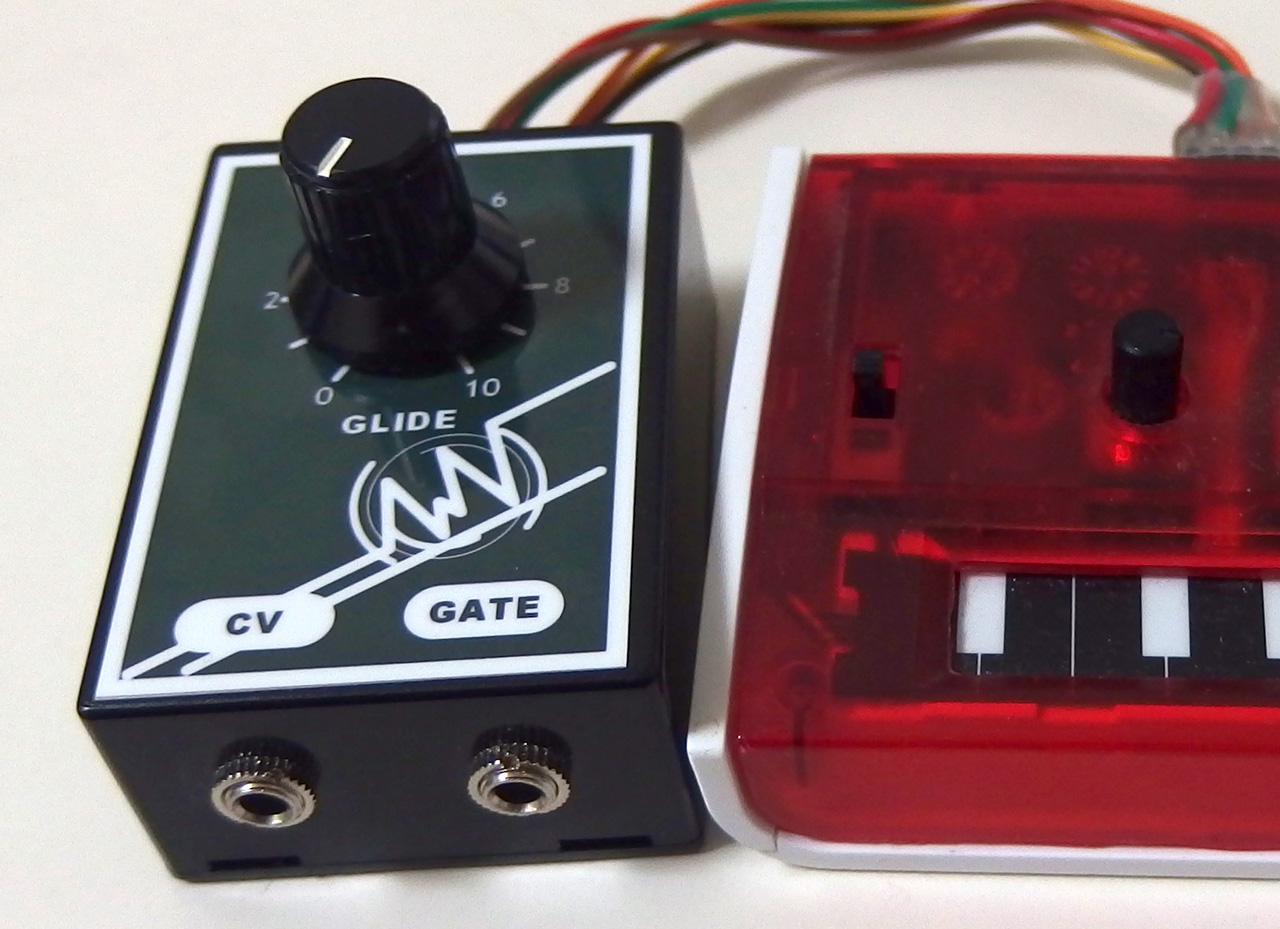
I add a portament function on it. I realy love the portament. I don’t need any volume knob. but I need portament knob. I hope that every synthe lover think as same as me.
この機器には、ポルタメント機能をつけました。ボリュームは無くてもかまわないけど、ポルタメントが無ければ、シンセとはいえないかもしれないぐらいに、ポルタメントは大事な機能だと思います。
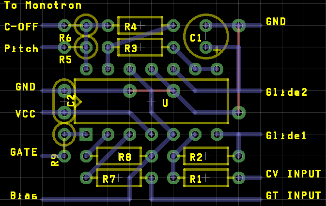
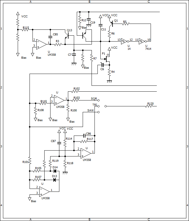
- Schematics for 1V/OCT adapter for monotron
- Pattern layout for 1V/OCT adaptor for monotron
- inside of enclosure
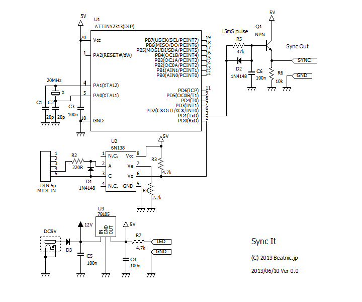
MIDI-IF
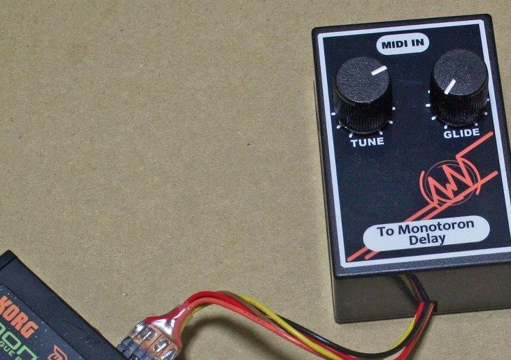
visit next page and put an order.
if you want to use this kit for monotron Delay, then order #207 Extra parts set for Monotron Delay with #200.
Picure shows how to put the kit into some encrosure. (the kit don’t include enclosure )
写真は、組み立てたキットを別のケースに入れたところです。(ケースはキットには含まれません)


